
Precursor
Let's start with a few quotes from Wikipedia to establish a baseline for this topic.
Voltage
Voltage, electric potential difference, electric pressure or electric tension (denoted ∆V or ∆U) is the difference in electric potential energy between two points per unit electric charge. The voltage between two points is equal to the work done per unit of charge against a static electric field to move the charge between two points and is measured in units of volts (a joule per coulomb).
Current
An electric current is a flow of electric charge. In electric circuits this charge is often carried by moving electrons in a wire.
Direct Current (DC) is the unidirectional flow of electric charge. The electric charge flows in a constant direction, distinguishing it from alternating current (AC).
The Implementation of Power over USB
USB connections provide power to the devices they are connected to, commonly seen by almost every USB drive and smartphone charger on the market today. The standards for USB2 allow the max voltage up to 20V (DC) (yes, 20V) and max current draw to be anywhere from 0.1A (100mA) to 5A (5000mA) depending on the implementation.
In almost every common situation as of the time of writing, USB2 ports will provide 5V and around 450mA with the exception of usb chargers at 500-1800mA - USB3 ports generally provide 5V and 900mA.
Of course there are exceptions. For example USB On the Go (USB-OTG), a mode where both devices operate without a standard host-only controller.
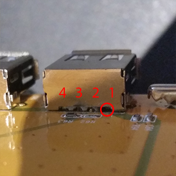
For reference, here is a diagram of common USB pinouts.
Starting at pin 1 is really hard when you count from 0 all the time.
This is common - every day people are familiar with charging/powering their devices from USB so what's the problem?
The Problem
Not all devices require power from the USB host device to operate, the use case here is a powered USB hub. That is a USB hub with its own power source, generally a DC wall adapter. Now since USB is DC, the active pin on your USB host connection should have current flowing from it, in the direction of the ground pin.
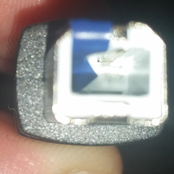
Using a PCB mount female USB A connector made testing much easier. Being upside down I'm testing pin 1 against the shielding. According to the greyness of USB standards. Should actually be grounded with low impedence to the devices ground? It's not really clear, but it's grounded somewhere.
Unfortunately, with budget devices this is not the case, as seen in the picture below.
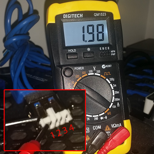
I ventured under the desk for this picture as the cables required for this rig were painstakingly cable tied in place.
As you can see, current is flowing from the powered device (hub) back down the cable into the host (computer) on pin 1. Right under 2V. I first noticed this when a powered USB hub was connected to a Raspberry Pi and the RPI was powered on despite having nothing connected to its power input. This also highlights an electrical flaw in earlier RPIs. Googling this scenario quickly identified the issue.
And that means?
Sometimes nothing, but after a while - 6 months in my case - it meant 2 dead USB controllers on my motherboard.

Solutions
Newer motherboards generally have protections against USB back-powering but for a long-term solution this certainly isn't something you want to bet on. In my case, to deal with the dead controllers, I purchased a new PCI USB2 controller for around $20.
Hacky electrical tape
 A quick fix is insulating pin 1 with some electrical tape.
Just be sure to entirely cover the pin with some overlap to make sure there is no connection and test it with your multimeter.
A 3-pin cable
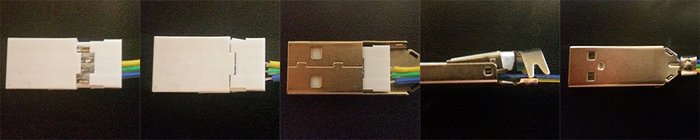
You can either expose and snip the active wire in the cable (usually colored red) or you can make yourself a 3-pin USB extension cable as shown below. 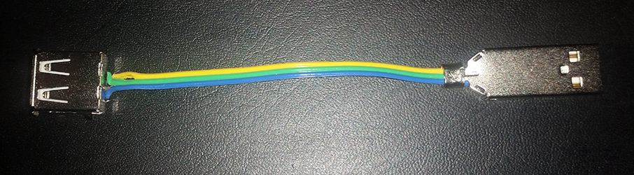
Components
- A short ribbon cable
- A USB A female connector
- A USB A male connector
- Basic soldering equipment
Cut and Tin both ends of the wire
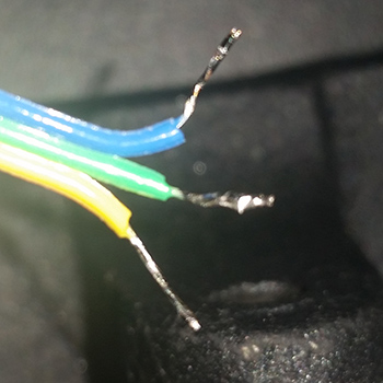
Start by cutting the ribbon to slightly longer than your desired length and split the ribbon so you only have 3 wires. Strip and separate the ends by 5-10mm, and tin them.
Solder the female connector
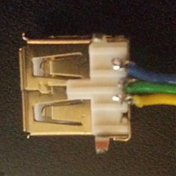
Make small hooks or loops with your pre-tinned wire and wrap them tightly around the legs of the female connector. Apply heat with your iron and a small amount of solder as necessary. Test continuity to make sure none of your pins are bridged.
Solder and assemble the male connector
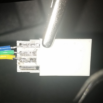
Match the pins on the connector here with the end you have already soldered (GND to GND, Data+ to Data+ Data- to Data-). Place each pin in its appropriate valley on the connector and apply heat. This should make the solder molten and flood the valley - apply enough solder to flood the valley neatly if required.
Now assemble and crimp the end of the connector with some pliers as show below.
Done
Test all your connections - make sure you check continuity between your ends and neighbouring pins. Now you can place this short cable between your host and device with assurance there is no back powering.
Desoldering the active pin
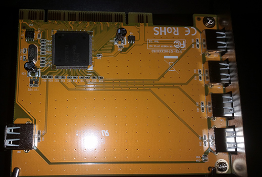
Finally, the most permanent solution - you can just desolder the active pin from either the device or the motherboard controller. In the example below I will do it to 4 ports on my PCI USB card.
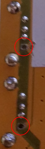
Cut the top of the leg
Start by cutting the top of the leg between the bottom of the female connector and the top of the PCB. I did this pretty much by pushing a small blade into the pin and with enough care and force it snapped fairly easily.
Remove solder from the Pin
Turn the board over and apply heat with your iron to the appropriate pin - the solder should turn molten.
In my case the solder used had a higher melting point than the solder I usually work with. To overcome this I applied some extra solder - when you apply heat, all the solder will become molten. Googling this phenomenon reveals many chemistry-focused answers, but start with fusable alloys like Field's metal.
Once the solder is molten, use a vaccum pump or braid to remove the remaining solder. If you're lucky, the leg will come with it. If not, just wiggle the leg back and forth like a tooth until it comes free.
Done
At this point test continuity between the female socket and the 5V line/pad and you should have no continuity. If you do still have continuity its just a matter of making sure there is no remaining leg near a trace/pad on the PCB. Do your best to make some clearance.
Not buying shitty hardware
This. It's important to take into account the max current draw of your devices when purchasing a USB hub - for example, if each device uses 450mA on a 10 port hub, thats 4500mA, though the DC adapter provided might only provide 1500mA. In this case it may shut off your devices as they are starved of power - the real problem is that the DC adapter will attempt to work harder, which will cause it to get hot and potentially overheat. This is also an issue with cheap DC adapters that are labeled with a higher rating than they can actually handle. It's usually a good idea to use a slightly higher rated adapter than you require.
Not to fear monger (while unusually using Sydney Morning Herald as a "News" source) seemingly harmless bargains can fucking catch fire.
Who's at fault?
- The host vendor for not protecting against back power ?
- The device vendor for allowing the back power in the first place ?
- Consumers, for buying shitty equipment ?
I'm going to go with all of the above. The name says it all, Universal Serial Bus. Meaning all vendors will stick with standards so "It just works". Everyone loves a bargain, but that's why knockoff / cloned hardware is available in the market. As a consumer I should know better than to buy no name brand hardware, even if the chipset is a trusted brand.
For a great read about forensics on knock off chips, take a look at this post on bunnie's blog