Pre-Ramble
Another Ruxcon has just passed and there was some awesome content that came through. We heard from @PanguTeam with some in depth details about their iOS work, David Jorm on Software Defined Networking, The White Australian Chris Rock on Hacking the Death Industry and Mark Dowd on delivering malicious, signed apps over Apple's AirDrop without authentication - among other great presenters and topics.
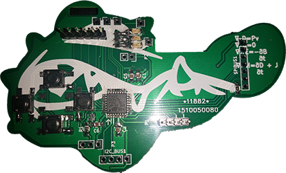
Though this was awesome, there was a new addition to this year. The Hardware Hacking Village, with our own badge you had to assemble yourself, connect to a programmer, cross compile some code, then write it to the chip. There was also a best hacked badge prize and with its success we are likely to see back again (I hope).
While all this cool stuff was going on, I spent most of the con hanging around track 1 writing code and updating databases for some of the events, as well as keeping an eye on the internal stream, so as you can imagine, I kindly asked someone to put a PCB+kit aside for me.
Now, at the hardware hacking village, manned by Dr Silvio himself, Aspect (I admire his lack of social media), Kylie with Peter Fillmore (the badge designer) floating around - even though he gave us a great talk on Apple Pay Security. There was some skill on hand for anyone who didn't know what they were doing when it comes to Surface Mount Components - which is me, and I should have at least grabbed the 101 - but in my usual style I didn't and decided to wing it.
Peter did publish an official guide, on github along with firmware examples - but I found while it was a good reference it isn't the be all and end all of documeation on such a wide topic.
A Few Minor Issues
I was missing a few vital things in my own kit when I got home, primarily: flux, a hot air station and a compatible programmer. Programming of the badge using OpenOCD and a buspirate v3 I'll cover in part 2 doesn't work out of the box, but I'll cover getting that to work in the next post.
The polarity of the LEDs is shown on the PCB with cathode on the right, beware, its not. This is mentioned in the assembly PDF.
Lots of youtube videos on surface mount soldering videos showed various methods of soldering components, but all of them seemed to always do 1 thing first. Flux the contacts. One of the primary reasons for this is all flux is tacky, that means your 2mm component isn't going to move around when you place it with your tweezers or suction device. I thought I'd just be more careful, and in the end it proved that it can be done, in 20x the time it would take normally.
The Blank PCB
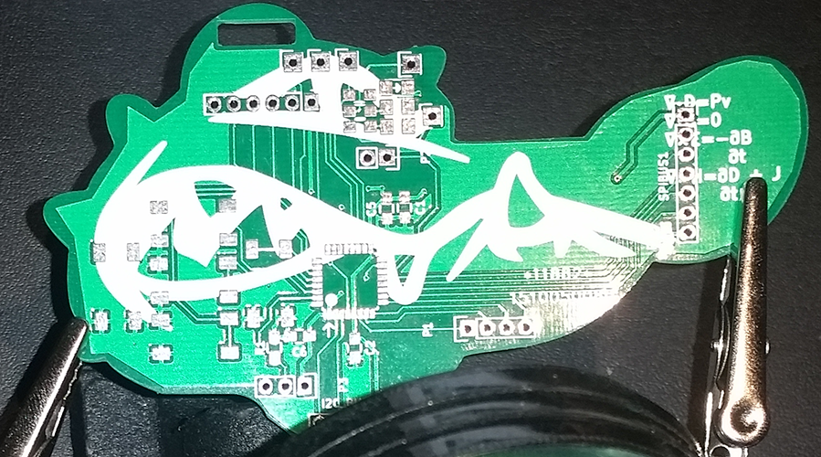
The design of the PCB was put together by Peter Fillmore, Schematics are in the github repo. At this stage, the first recommendation is applying flux to the pads and lightly tinning them. I didn't do this since I had no flux.

Component Used
- The Blank PCB (shaped as a Ruxcon Croc)
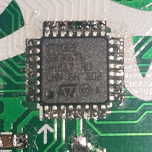
- The microcontroller, an ARM STM32f0x a nice little 32bit chip with 32k of flash memory.
- A row of headers, I used 10, but you may require more or less based on your end goal, mine was programming (I2C) and UART, skipping SPI
- 4× push button switches, you could use 5 - I only built a d-pad.
- 3× LEDs - I used one green, one orange and one red.
- 2× 100kΩ resistors
- 3× 470Ω resistors (missing from my kit, I'll cover these later on)
- 3× 0.1µF capacitors
- 1× 1µF capcitor
- 1× battery holder + CR2032 3v battery
Tools I used

- Variable heat soldering iron, set to 300C, with a pretty standard B series tip.
- Iron stand/station, so you dont have to fumble around trying to put a blazing hot iron down.
- Solder, 60% Tin 40% Lead 0.7mm.
- Third hand with magnifying glass, the magnification isn't that strong this cost me around $5 online but magnification will make all the difference with keeping your hands steady.
- Copper wire tip cleaner in a stand.
- Vacuum desoldering pump.
- Budget desoldering braid. (though I didnt require it since I prefer the pump)
- Multimeter, Used for checking continutity, polarity, resistance, capacitance and voltage.
- Tweezers, You need these. Especially if they have an angled nose.
Tinning the pads for the microcontroller
For this i used the drag method, by applying a blob of solder to the tip of the iron and lightly swiping from left to right across the pads, evenly distributing the solder across the pins. If too much solder is applied here this is where the vacuum comes in over the braid as it tends to always leave some solder behind. If you dont have enough solder here, just repeat the steps. Even though I'd never used this method before, after the first set of pads I managed to do the other rows on the first try.
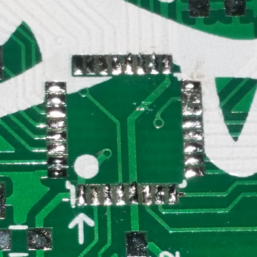
Watching a video of someone using this technique will give you a good idea of what to expect when using this method.
Checking your work
One common problem that can occur here is tin bridges, so be sure to check with magnification and continuity testing that each pin does not share continuity with either of its partners. The quickest way to do this I found was to place one probe on pin 0, then test pin 1 - next move to pin 1 and test pin 2. wash, rinse, repeat.
If you find that there is a bridge, just lightly swipe your iron in the gap and it should sort itself out thanks to the natural cohesive properties of molten solder.
Soldering the microcontroller
I imagine this step would have been much easier with flux, but it wasn't too bad. The technique was aligning the dot on the chip with the pin marked as 0 on the PCB.
Just settle the microcontroller in place so the feet align with the pads using your tweezers, and gently press down in one corner with your iron for a brief moment, just long enough to make the solder molten again. Once you have done this, check all your feet align with the pads again, and then check again, and then check again. If you're not satisfied with the positioning, apply heat again to the initial tack you made and reposition with tweezers. Switch to the opposite side of the chip (you probably want to turn the board around 180 degrees in the 3rd hand) and tack the opposite corner in the same way as the first.
Remember, you don't need to apply much pressure or much time to each tack, easy does it.
Once you have done that, do the same thing for the rest of the pins. The end goal is to have a nice strong bond that covers all the way from the back of the foot to the front of the foot on each leg of the microcontroller.
Checking your work
Now check the end of each pad (without touching the foot) and the top of each leg for continuity with the multimeter.
Again the first time I had done this technique, the hardest part is only the initial alignment.
When you're ready to move on, check each pin again for continuity with its neighbour, but this time, use the top of the leg and the bottom of the neighbouring foot. If there are no bridges you can move on.
Soldering the LEDs.
Warning. This is the only component on the board (besides the microcontroller) that the polarity must be correct. The direction printed on the PCB is backwards.
We can go straight to the the official documentation for this one, following step 4.
I placed the green LED at the top, orange in the center and red at the bottom, I figure with this configuration it could be used as a health bar, a battery indicator, a scroll bar or even just TX/RX activity and Power.
Checking your work
Set your multimeter to continuity mode, if you connect the com to the cathode and the active probe to the anode side the LED will light up. Make sure the cathode side is on the LEFT.
Soldering the other passive components
Soldering these smaller components will definitely require the tweezers, fluxing the pads here will also help as the area with flux applied will become tacky.
These components do not have a specific polarity (non-polarised) to operate, so this is probably the easiest part of the assembly.
Rather than regurgitate these steps for the passive components, reference the official documentation. Follow steps 5, 6 and 7 - this should thoroughly cover the process needed.
Identifying resistors visually
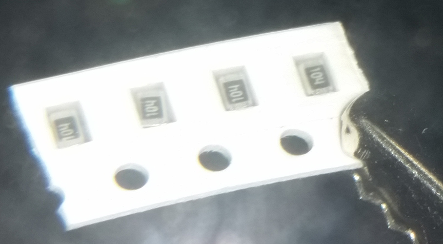
This is kind of hard if you haven't done it before, but looking under magnification at your resistors will identify them for you. On larger resistors a colored band system is used to reference and calculate the resistance. On SMD resistors you can use a similar method to use the number values to calculate the resistance. Pictured below you can see 100kΩ resistors labeled 104. There is a nice calculator with extended definitions here
Checking your work
First check continuity with your multimeter between the end of the pads on either side of the component, this will ensure your connections have been made successfully.
Resistance
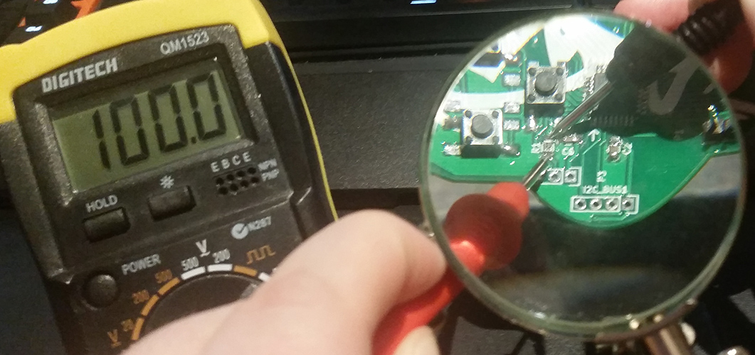
Resistance is super easy to check - set your multimeter to the relevant Ω setting, testing the 100k resistors first - located at R1 and R12 - I've set my multimeter to the 200KΩ setting.
Do this again for your 100Ω resistors
In my case, the 100Ω resistors for R13, R14 and R15 were missing from my kit but also aren't totally necessary. I bridged them with wire to compensate.
Capacitance
This is a litte trickier than testing resistance, so I'll break it down into a few easy steps. In our favour the caps used in this project are not polarised.
Make sure the circuit is not powered for this step! Also make sure you are testing from the end of the pad and your probes are not connected directly to the capacitor itself.
10: Checking the current voltage stored in the capacitor
If you haven't previously connected power to the device this should be zero - however its always good to check and double check everything you do. Start by reading the voltage of the capacitor, for this I have my multimeter set at 2V - if its zero, GOTO 40.
20: Draining the capacitor
Since we are only working with non-polarised 0.1µ and 1µ capacitors we can drain these with a small resistor, in my case I'm using a spare 100kΩ. On larger caps, this can much more dangerous since they can store quite the charge - so on a larger project I would recommend taking all the safety precautions to prevent being shocked and using at least a 20kΩ 5 watt resistor. Connect the resistor to each side of the capacitor for 5 seconds.
30: Checking the current voltage stored in the capacitor
GOTO 10
40: Charging and reading the capacitor with your multimeter
Set your multimeter to 20kΩ and watch the readout increase. Next you can set the multimeter back to 2V to read the stored voltage again.
Soldering the buttons
Again, we can go straight to the the official documentation for this one, following step 8.
Checking your work
Simple continuity testing here will work just fine, when the button is pressed the 2 diagonal pads should have continuity and the 2 non-connected pads should be the same.
Populating headers
This is standard through hole soldering one of the simplest techniques to master when it comes to a PCB - in my experience with hardware hacking, populating headers is probably the most common task that needs to be performed on SOHO routers and other embedded devices, There are lots of guides online on how to do this so I won't cover it here.
The header you will need to populate for programming the chip is P6 - a 6 pin header, located at the top of the PCB.
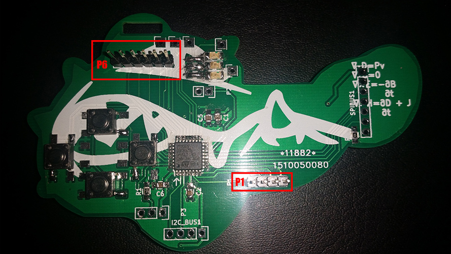
I have also chosen to populate P1, a 4 pin header on the lower right which I intend to use for UART. It's really up to you at this point if you want to populate the other headers for SPI and I2C based on the other hardware you plan to integrate with.
Checking your work
The best way to check continuity between your new pins is to check the PCB schematic. Check continuity from the top of the pin on the header to the top of the leg on the microcontroller.
Connecting the battery
Again, we can go straight to the the official documentation this time following step 9.
Checking your work
At this point our circuit has power and the microcontroller is operational ready to be programmed. We can test our battery connection by checking the voltage between any ground pin and pin 1 on the MCU.
Congratulations - You're done!... with assembly.
Conclusion
I actually thought this project would be hard as my electronic skills are far from professional. I was quite surpirsed to find that it was easy. Some basic electronics background is good to have but even having none the documentation and the knowledge of the guys at the hardware hacking village could easily get you through it in under an hour. I recommend next year anyone even slightly interested in embedded computers or electronics to take a jmp over one of the talks and spend some time in the village putting a badge together. Overall it was a great learning experience and excellent starter supplement any hackers skillset.
Part 2: Programming the chip
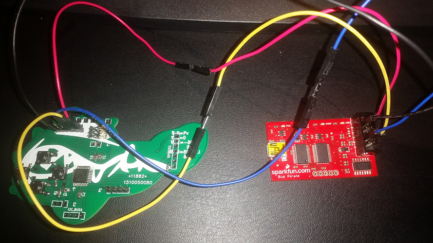
Click over to Ruxcon Badge 2015 Part II: Programming where I cover setting up the toolchain for cross compilation, installing OpenOCD for programming and debugging and using a Bus Pirate to get the job done.